Deutsch
 Magyar
Jetter peripherals
Jetter-Peripherals
JX2-Module
JX3-Module
JX6-Module
JX6-Submodule
JX2 modules
The JX2 system offers a range of classic expansion modules for the automation of devices and systems.
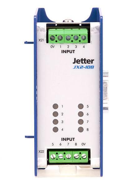
JX2-ID8
Digital input module for centralized or decentralized applications.
Specifications:
| Number of inputs | 8 |
| Input signal voltage | 0…30 V DC |
| Power Consumption | 15 mA / 24 VDC |
| Input current | about 8mA |
| Input resistance | 3.0kΩ |
| Input latency | about 3ms |
| Input signal voltage | ON min 11V, OFF max 5V |
| Voltage Isolation | None |
| Connect to base device | On the system bus, 9-pin SUB-D connector |
| Wire inputs | Bolt Binding |
| garden shed | Metal |
| Dimensions (WxMaxT) | 45x115x69mm |
| Montage | on DIN rail |
| Heat Loss | 0.3W |
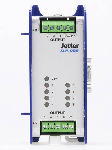
JX2-OD8
Digital output module for centralized or decentralized applications.
Digital output module for centralized or decentralized applications.
- 8 digital outputs 24V DC / 0.5A PNP
- The 24V DC switching voltage is connected separately
Download data sheet
Technical data:
| Number of outputs | 8 |
| Outputs type | PNP transistor |
| Output signal voltage | 20…30V DC |
| Power Consumption | 15mA / 24V DC |
| Output current | max. 0.5A / output |
| Output power | 96W |
| Voltage Isolation | None |
| Protection | Short circuit, overvoltage, overheating |
| Inductive load protection | There is |
| Output voltage in ON state | tip. supply voltage -1.5V |
| Connect to base device | On system bus, 9-pin SUB-D connector |
| Wire outputs | Bolt binding |
| Wiring connected voltage | Bolt binding |
| Device House | Metal |
| Dimensions (WxMaxD) | 45x115x69mm |
| Assembly | to DIN rail |
| Heat loss | 0.3W |
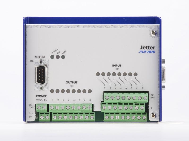
JX2-IO16
Digital I/O module for managing inputs and outputs and receiving fast pulses. It must be supplied with a 24V DC power supply, so it can supply 3 additional non-intelligent modules with power. Download data sheet.</ a>
Digital I/O module for managing inputs and outputs and receiving fast pulses. It must be supplied with a 24V DC power supply, so it can supply 3 additional non-intelligent modules with power. Download data sheet.</ a>
- 4 digital inputs (24V DC) with pulse extension
- 4 fast digital inputs (24V DC) with pulse extension and counter function
- 8 digital outputs (24V DC)
- 3-level terminal blocks for direct connection of sensors and actuators
Download data sheet
Technical data:
| Number of inputs | 8 |
| Input signal voltage | 0…30V DC |
| Incoming current | approx. 8mA |
| Input Resistance | 3.0 kΩ |
| Voltage level in ON state | min. 16V |
| Voltage level in OFF state | max. 5V |
| Pulse length min. (5-8 in.) | 250μs |
| 1-channel counter max. freq. | 2kHz |
| 2-channel counter max. freq. | 1kHz |
| Number of outputs, type | 8, transistorized (PNP) |
| Rated voltage | 24V DC, -15%…+20% |
| Rated output current | 0.5A |
| Protection | Against inductive load, short circuit, over voltage and overheating |
| Output voltage in ON state | tip. supply voltage -1.5V |
| Voltage Isolation | None |
| Connect to base device | On system bus, 9-pin SUB-D connector |
| Wiring Inputs/Outputs | Bolt binding |
| Device House | Metal |
| Dimensions (WxMaxD) | 130x1103x47mm |
| Assembly | to DIN rail |
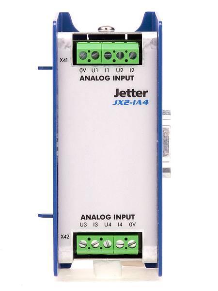
JX2-IA4
Management of analog inputs, for measuring voltage and current.
Management of analog inputs, for measuring voltage and current.
- 4 analog inputs, selectable input signal
- 0-10V, ±10V (12 bits)
- 0-20 mA (11 bits)
Download data sheet
Technical data:
| Number of inputs | 4 channels, U1-4 for voltage, I1-4 for current |
| Voltage range | 0-10V (0…4095), ±10V (-2048…2047) |
| Voltage signal resolution | 12 bits |
| Voltage Input Impedance | Unipolar: 21kΩ, Bipolar: 16kΩ |
| Current range | 0-20mA (0…2047) |
| Current signal resolution | 11 bits |
| Current Input Impedance | 220Ω |
| Voltage Isolation | None |
| Power Supply | In Köponzi application: from the base device, in decentralized application: from the power supply |
| Connect to base device | On system bus, 9-pin SUB-D connector |
| Wire inputs | Bolt binding |
| Device House | Metal |
| Dimensions (WxMaxD) | 45x115x69mm |
| Assembly | to DIN rail |
| Heat loss | 0.3W |
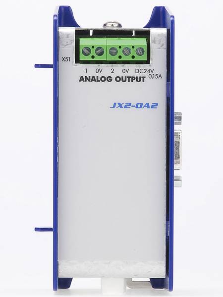
JX2-OA2
For handling analog outputs, voltage signal. Download data sheet.</ a>
For handling analog outputs, voltage signal. Download data sheet.</ a>
- 2 analog outputs
- Output voltage: ±10V
Download data sheet
Technical data:
| Number of outputs | 2 |
| Voltage range |
±10V (-2048…2047)
|
| Voltage signal resolution | 12 bits |
| Power Supply | 24V DC, -15%…+20% of analog outputs |
| Output current | max. 10mA |
| Delay Time | < 4ms |
| Voltage Isolation | None |
| Zero point error | max. ±6 LSB 29.3mV |
| Validation error | max. ±6 LSB 29.3mV |
| Power Supply | In Köponzi application: from the base device, in decentralized application: from the power supply |
| Connect to base device | On system bus, 9-pin SUB-D connector |
| Wire inputs | Bolt binding |
| Device House | Metal |
| Dimensions (WxMaxD) | 45x115x69mm |
| Assembly | to DIN rail |
| Heat loss | 0.3W |
JX2-OA4
For managing analog outputs. Stress signal. Download data sheet.</ a>
For managing analog outputs. Stress signal. Download data sheet.</ a>
- 4 analog outputs
- ±10V (12 bits)
Download data sheet
Technical data:
| Number of outputs | 4 |
| Voltage range |
±10V (-2048…2047)
|
| Voltage signal resolution | 12 bits |
| Power Supply | 24V DC, -15%…+20% of analog outputs |
| Output current | max. 10mA |
| Delay Time | < 4ms |
| Voltage Isolation | None |
| Zero point error | max. ±6 LSB 29.3mV |
| Validation error | max. ±6 LSB 29.3mV |
| Power Supply | In Köponzi application: from the base device, in decentralized application: from the power supply |
| Connect to base device | On system bus, 9-pin SUB-D connector |
| Wire inputs | Bolt binding |
| Device House | Metal |
| Dimensions (WxMaxD) | 45x115x69mm |
| Assembly | to DIN rail |
| Heat loss | 0.3W |
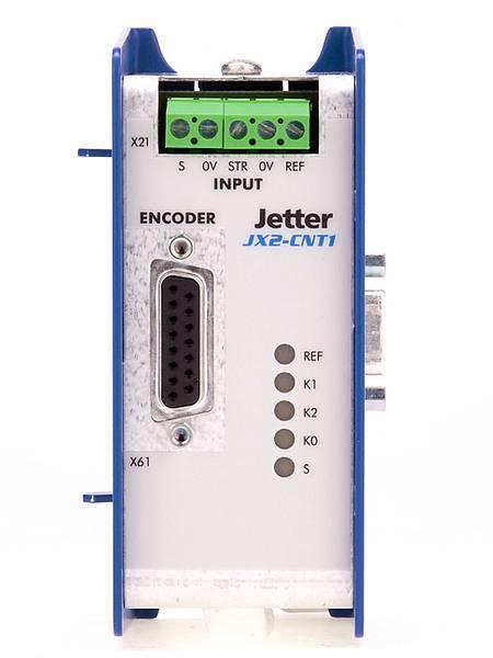
JX2-CNT1
Counter module for counting events. The module has one-channel and two-channel counters. The single-channel counter, e.g. for counting the number of pieces, and the two-channel counter e.g. can be used for length measurement.
Counter module for counting events. The module has one-channel and two-channel counters. The single-channel counter, e.g. for counting the number of pieces, and the two-channel counter e.g. can be used for length measurement.
- 1 single-channel counter, max. 10kHz
- 1 two-channel counter (can be used as a single-channel counter)
- max. 500kHz at 24V
- max. 1MHz at 5V
- Special functions
- As master for JX2-SV1 or CAN-DIMA module
- Capture function
- SSI absolute road transmitter (Gray and binary code evaluation)
Download data sheet
Technical data:
| Number of counters | 1 only. account., 1 double buckle. account. |
| One tap. account. max. freq. |
10kHz
|
| One tap. account. voltage level | 24V |
| Two-Chat. account. max. freq. | 500kHz at 24V, 1MHz at 5V |
| Two-Chat. account. voltage level | with 24V switching level: ON min. 15V, OFF max. 10V, 5V differential voltage |
| Voltage Isolation | None |
| Power Supply | 20…30V DC |
| Connect to base device | On system bus, 9-pin SUB-D connector |
| Wire inputs | Screw connection, 9-pin SUB-D connector |
| Device House | Metal |
| Dimensions (WxMaxD) | 45x115x69mm |
| Assembly | to DIN rail |
| Heat loss | 0.5W |
| Incr. in. heat loss | 0.5W |
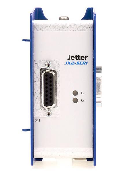
JX2-SER1
Freely programmable serial PRIM connector for integrating devices with a serial port, e.g. to query balance sheet data.
Freely programmable serial PRIM connector for integrating devices with a serial port, e.g. to query balance sheet data.
- Freely programmable connectors: RS232, RS422/485
- Software and hardware handshake mode
- Receiving buffer 129 bytes (FIFO) sending buffer 128 bytes (FIFO)
Download data sheet
Technical data:
| Freely programmable connector | 15-pin connector; RS232: 150…57,600 Bit/s or RS422: 150…115,200 Bit/s or RS485: 150…115,200 Bit/s |
| Connect serial port |
15-pin SUB-D connector
|
| Rated current consumption | approx. 70mA |
| Voltage Isolation | None |
| Power Supply | In Köponzi application: from the base device, in decentralized application: from the power supply |
| Connect to base device | On system bus, 9-pin SUB-D connector |
| Device House | Metal |
| Dimensions (WxMaxD) | 45x115x69mm |
| Assembly | to DIN rail |
| Heat loss | 0.35 W |
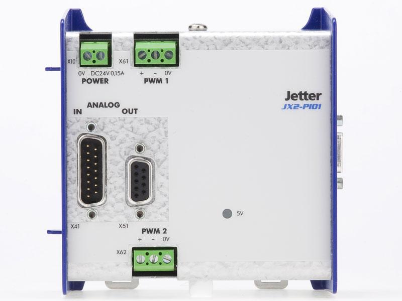
JX2-PID1
The digital JX2-PID1 module is used to control processes in automation. For example: for temperature regulation or air pressure regulation.
The digital JX2-PID1 module is used to control processes in automation. For example: for temperature regulation or air pressure regulation.
- 4 analog voltage inputs
- 4 analog current inputs
- 4 analog outputs
- 4 unipolar PWM outputs
- 4 internal PID control loops
Download data sheet
Technical data:
| Power Supply | 20…30V DC |
| Power Consumption |
140mA / 24V
|
| Cycle Time | min. 2ms per controller; For 4 controllers, 8ms per controller |
| A/D converter | Voltage: unipolar or bipolar, 12-bit resolution 100k sample/s; current: unipolar, 12-bit resolution 100k sample/s |
| D/A converter | Bipolar, 12-bit resolution; unipolar, 11-bit resolution |
| Number of inputs | 4 voltage, 4 current |
| Voltage range (inputs) | 0…+10V (unipolar), -10…+10V (bipolar) |
| Current range | 0(4)…20mA |
| Input Resistance | Voltage: 20kΩ, Current: 100Ω |
| Number of outputs | 4 analog outputs, 4 PWM outputs |
| Voltage range (outputs) | 0…+10V (unipolar) -10…+10V (bipolar) |
| Loadability | DAC: 10mA, PWM: 300mA |
| PWM outputs | Open colleltor |
| Connect to base device | On system bus, 9-pin SUB-D connector |
| Connect inputs | 15-pin SUB-D connector |
| Connect Outputs | DAC: 9-pin SUB-D connector, PWM: screw connection |
| Connect Power | Bolt binding |
| Device House | Metal |
| Dimensions (WxMaxD) | 105x115x69mm |
| Assembly | to DIN rail |
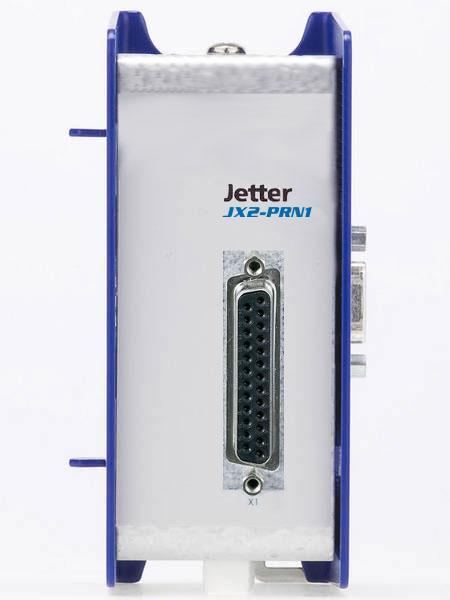
JX2-PRN1
Printer module, for data exchange and printing with printers.
Printer module, for data exchange and printing with printers.
- Centronics printer port
Download data sheet
Technical data:
| Centronics connector | 25-pin connector |
| Power Consumption |
35mA / 24V DC
|
| Voltage Isolation | None |
| Connect to base device | On system bus, 9-pin SUB-D connector |
| Device House | Metal |
| Dimensions (WxMaxD) | 105x115x69mm |
| Assembly | to DIN rail |
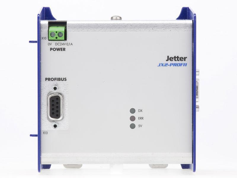
JX2-PROFI1
Can be used as a Profibus slave. It can be freely programmed and parameterized in the user program.
Can be used as a Profibus slave. It can be freely programmed and parameterized in the user program.
- Profibus slave
- 12 MBaud
Download data sheet
Technical data:
| Profibus | Slave operation |
| Baud Rate |
12MBaud
|
| Power Supply | 20…30V DC |
| Power Consumption | 100mA / 24V DC |
| Connect to base device | On system bus, 9-pin SUB-D connector |
| Bindings | Power supply: screw connection, Profibus: 9-pin SUB-D connector |
| Device House | Metal |
| Dimensions (WxMaxD) | 105x115x69mm |
| Assembly | to DIN rail |
| Heat loss | 0.3W |
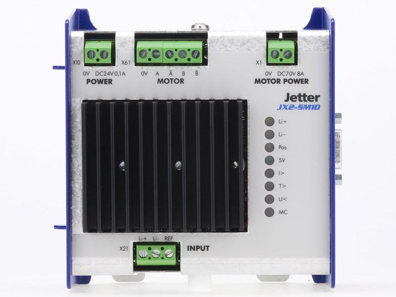
JX2-SM1D
The stepper motor output stage is an intelligent expansion module for stepper motor shaft with integrated output stage for 2-phase stepper motor.
The stepper motor output stage is an intelligent expansion module for stepper motor shaft with integrated output stage for 2-phase stepper motor.
- Position control and 70V / 5A output stage for 2-phase stepper motors
- Positioning range -8,388,608…+8,388,607 steps
- Max. step frequency 25 kHz
- Start/Stop ramp linear, programmable
- Catch function
Technical data:
| Positioning Range | -8,388,608…+8,388,607 |
| Step Rate | max. 25 kHz |
| Start/Stop Ramp | Linear, programmable |
| Step resolution | 1/1, 1/2, 1/4, 1/8, 1/16 |
| Reference Motion | max. step frequency 1000 Hz |
| Motor current (phase current) | Can be adjusted in steps of 0.5…5A (0.3A) |
| Motor operating voltage | 24…70V DC |
| Output stage switching mode | bipolar |
| Power Supply | 20…30V DC |
| Power Consumption | 85mA / 24V DC |
| Connect to base device | On system bus, 9-pin SUB-D connector |
| Connect | Bolt binding |
| Device House | Metal |
| Dimensions (WxMaxD) | 105x115x69mm |